Engine
H394 Series TEMPCAL® Tester
BH112JD Series JETCAL® Engine Analyzer/Trimmer
Industries Served
- Military
- Commercial
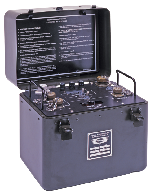
H394 Series TEMPCAL® Tester
Multi-Range Thermocouple and Thermal Switch Tester
Thermocouple, thermal switch, continuous wire fire/overheat loop testing
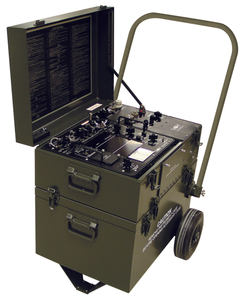
BH112JD Series JETCAL® Engine Analyzer/Trimmer
Portable and self-contained, the Jetcal® Analyzer/Trimmer consists of a compartmented accessory case and an instrument case with removable trim module. Instructions for use of the Jetcal® Analyzer/Trimmer are contained within the case.
Specifications
H394 Series TEMPCAL® Tester
Features
Portable, lightweight, at aircraft testing for engine thermococuples, system thermal switches and heat sensing overheat wire loops. Adapatable to hundreds of devices with appropriate heater probe accessories.
Specifications
- Indicating range:
-40 to 1850 °F
-40 to 1010 °C - Indicator Accuracy: ±1 °C in Normal Operating Conditions of 50° to 95 °F
- Dimensions: 14” H x 9.7” D x 12” W
- Weight: 25 lbs
- 115 -240 VAC
Specifications
BH112JD Series JETCAL® Engine Analyzer/Trimmer
Features
- Input Parameter Flexibility
- Engine test parameters – temperature, speed, and pressure
- Speed/Frequency Measurement
- Temperature/Standard Day Calculation
- Pressure/EPR System
- Data Printout
- Temperature Indicator Test
- Thermocouple Harness Tests
- JD Series may be ordered with various power, input, printer, accessories and other configurations.
Specifications
| Parameter | Range | Programmable Display Range | Accuracy |
| Engine Temperature (type K cr-al t/c) | 0 to 1350°C (0 to 2465°F) |
0 to 1350°C (0 to 2465°F) |
±2°C ±4°F |
| Engine Temperature (TF30 cr-al curve) |
0 to 1360°C (0 to 2480°F) |
0 to 1360°C (0 to 2480°F) |
±2°C ±4°F |
| Standard Day Temp | -60 to 100°C ambient |
———- | ±4°C @ 600°C |
| Ambient Temperature | -60 to 100°C (76 to 212°F) |
-60 to 100°C (76 to 212°F) |
±0.3°C ±0.5°F |
| Frequency | 10 to 30K Hz | 32,760 counts max (%RPM, RPM, PPH, HZ) |
±0.1% |
| Standard Day Freq | -60 to 100°C ambient |
———- | ±0.2% RPM @ 70 Hz=100% |
| Internal Pressure Transducer | 0 to 5 vdc | 0 to 101.8
IN.HG. ABS 0 to 50.00 PSIA |
±0.25
IN.HG.
±0.12 PSIA |
| External Pressure Transducer (BH21217) | 0 to 6.200 vdc | 9,999 counts max (IN. HG., PSI, PCNT., FT.LB.) | ±0.2% |
| Engine Pressure Ratio | 0.800 to 3.500 | ———- | ±0.05 |
| Resistance | 0 to 40 ohms | ———- | ±0.04 ohms |
| Insulation Resistance | 0 to 200K ohms | ———- | ±2K ohms |
| Temperature Indicator Calibration Signal | 50 to 1000°C | ———- | ±2°C |
Power Requirements:
- Probe Control Unit Assembly
- Two different models are supplied, one operates from 115vac, 50-400 Hz and the other model from 230vac, 50 Hz. The power requirement for each model is marked on the Probe Control Unit at the Power Input Connector.
- Trimmer Assembly
- 115vac, 50-400 Hz or 28vdc
Dimensions in Inches: 22.5 long by 21 wide by 23.5 high (excludes handle)
Weight: 90lbs (excludes assessors; add 4.5lbs for internal printer)
Download Brochures
For more information, download the product brochures.